

Testing of a two-span reinforced concrete beam
HOME PAGE - RESEARCHES - TESTING OF A TWO-SPAN REINFORCE...
Study of the impact of reinforcing plasticity on the behavior of a two-span reinforced concrete beam
Aim and assumptions for research
The aim of the study was to determine the differences in the behavior of a two-span reinforced concrete beam depending on the mechanical parameters of reinforcing steel class A and C (according to Eurocode 2).
The tests were performed on two sets of research elements consisting of two beams each. As part of each set of beams, the use of a different classes of reinforcing steel was assumed. In the tests, it was assumed that each class of steel was called respectively: SI and SII. Classes of reinforcing steel used for reinforcement of research models are presented in the table below.
| SI |  |
Class C (according to Eurocode 2) hot rolled steel EPSTAL |
| SII |  |
Class A (according to Eurocode 2) cold rolled steel |
A symmetrical load of each span of beams was assumed with four concentrated forces according to the diagram shown in Fig. 1. The position of concentrated forces was chosen so as to reproduce the uniformly distributed load as accurately as possible.

Fig. 1 Load schemes of models
As the primary variable parameter (varying models) assumed steel class of longitudinal and transverse reinforcement. The remaining parameters, such as the reinforcement ratio of longitudinal and transverse reinforcement, the strength of the concrete, the method of load implementation were assumed to be the same for all beams in both sets of models. The test elements were adopted from ordinary concrete on pebble aggregate with compressive strength corresponding to class B-25.
Models for testing
Sets of research elements depending on the class of reinforcing steel used are marked with the symbols BI (steel SI) and BII (steel SII). Each research set consisted of two monolithically made beams (BI-1, BI-2 and BII-1, BII-2) with a rectangular cross-section of 0.4 x 0.2 m and a total length of 8.80 m. Beam support was carried out with three supports at an axial distance of 4.0 m (two end supports were placed symmetrically with the inner support located in the center of symmetry of each beam), thus obtaining a continuous two-span structure with two 0.4 m supports on each side of the extreme beam support. Model reinforcement consisted of straight, longitudinal reinforcement bars Ø12mm in diameter and stirrups Ø10mm in SI and SII steel. The stretched longitudinal bars were anchored at the ends (in the compressed zones of the cross section) by adhesion or by means of transversely welded rods with a diameter of 12 mm. In each of the models, the same percentages of longitudinal reinforcement were used, equal to ρ1 = 0.46% in spans (3φ12mm) and ρ2 = 0.31% (2φ12mm) over the internal support. Transverse reinforcement consisted of stirrups perpendicular to the beam's axis (made of the same class of steel as longitudinal reinforcement) of Ø10mm in diameter. The longitudinal spacing of the stirrups was chosen so that the bearing capacity of the support cross-section could not be lost due to transverse forces. At the extreme supports, the spacing was constant and amounted to s1 = 0.1 m. At the inner support, the spacing varied from s1 = 0.1 m to s1 = 0.217 m. In compressed zones of span cross-section of beams, in which strain of tensile steel was measured, assembly reinforcement was not used. In the support cross-section (on a distance of 80 cm), the stirrups were stabilized for the time of concreting with Ø5mm wires made of St0S steel placed in the neutral axis of the cross-section of the beam (20 cm from the horizontal edges of the cross-section). In the middle of the span length of 80 cm, no longitudinal or transverse reinforcement was used. The reinforcement construction drawing is shown in Fig. 2. The cover of all bars from longitudinal reinforcement was cnom = 25 mm, and transverse reinforcement cnom = 15 mm and in all beams was the same.

Fig. 2. Reinforcement of research models
Test stand
The models were tested in a specially made stand, the main components of which were the furnishings of the Chair. The view of the test stand is shown in Fig. 3, while the detailed sketches on which detailed sketches without safety supports are shown in figures 4 and 5.

Fig. 3 View of the test stand
The stand consisted of two steel frames positioned transversely to the beam's axis with a spacing of 2.25 m. Bolts to the two frames is attached horizontal steel bolt length 4.20 m made of a profile rolled I550, which served as a support for two hydraulic cylinders. Hydraulic cylinders with a range of 1000 kN each were placed at a spacing of 4 m in such a way that they were in the axis of the span of the research models. The vertical load was transferred to CT 25 dynamometers with the range of 250 kN, and then by means of steel load distributors - traverses in the form of 4 equal concentrated forces applied to the research element. A two-tier arrangement of traverses - the first and the second row in each span of the beam was used. First-order cross-bars that separated the load from the actuator into two equal parts were made as welded two I-sections 220 in length of 2.20 m. These elements were loaded by steel movable second traverse rollers, which were based on the upper surfaces of the beams, finally separating the vertical load into four equal concentrated forces in each beam span. These elements were made of two HEB 100 I-beams welded together with a length of 0.9 m.

Fig. 4 Test stand view A-A

Fig. 5 Test stand, B-B view
Concentrated forces transferred directly to the research models were transferred through a set of bearings placed in such a way that an articulated sliding bearing was located in the areas of the highest rotation predicted. To ensure safety during the tests and to protect the element from falling from the props of the station, temporary supports were used in two places of each span. In addition, all the steel elements through which the load was generated were pivoted to the transverse bolt attached to the transverse frames. The research model was based on three supports - two extreme ones marked as A and C and one internal B (figures 10 and 11). The supports A and C were located symmetrically in relation to the support B at a distance of 4.0 m. They consisted of a concrete block measuring 0.4 x 0.4 x 1.10 m on which steel plates were placed on the cement mortar layer, supporting the force meters or bolts rectification. Details of the supports are shown in Figure 6-8.
Supports
The extreme support A was made as articulated sliding. The possibility of rotation was ensured by spherical joints in which two electromagnetic force meters CT 10 with a range of 100 kN were provided. The gauges were placed on a steel plate resting on two steel rollers that ensure free movement of the beam. Force meters allowed for continuous measurement of the reaction.

Fig. 6 Scheme and view of the support A
The internal support B was constructed in a slightly different way than the extreme support A. Through the arrangement of two measuring force CT 25 with a range of 250 kN, rotation was ensured while the steel support plates prevented levels of beam transfers on the support.

Fig. 7 Scheme and view of the support B
Extreme support C articulated - sliding was equipped with two rectification screws with articulated heads. The bolts are based on steel plates resting on steel rollers. On this support, the research model was rectified after setting up on the test bench.

Fig. 8 Scheme and view of the C support
Load method and force measurement
Before proceeding to the main part of the research, the test models were weighed using a bow dynamometer pivotally attached between the special sling and the crane hook, determining the own weight of each "G" beam. A schematic sketch of the measurement of the weight of the beam is presented in Fig. 9. Then the steel elements of the "GL" and "GP" stands were weighed, which were in the course of research on the research models.

Fig. 9 Measuring the own weight of the beam
Next, the research models were placed on supports and rectified in the "C" support so as to obtain values close to those determined in the theoretical way. The static scheme of the test models with permanent loads is shown in Fig. 10, and the values of permanent loads and initial reactions measured before the basic tests are presented (own weight + steel elements) are presented in table 1.
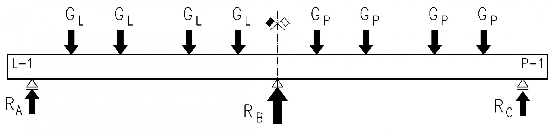
Fig. 10 Permanent loads
Table 1. Permanent loads and initial loads of research models.
| Element |
G [kN] |
GL [kN] |
GP [kN] |
RA [kN] |
RB [kN] |
|||
|---|---|---|---|---|---|---|---|---|
| cal
|
test
|
cal | test | cal | test | |||
| BI-1 | 17,64 | 17,72 | 0,53 | 0,52 | 4,636 | 4,595 | 12,622 | 12,394 |
| BI-2 | 17,64 | 17,64 | 4,622 | 4,378 | 12,577 | 12,563 | ||
| BII-1 | 17,64 | 17,56 | 4,604 | 4,572 | 12,532 | 12,555 | ||
| BII-2 | 17,64 | 17,64 | 4,622 | 4,548 | 12,577 | 12,667 | ||
In the main part of the research, the models were tested in accordance with the scheme shown in Figure 11.

Fig.11. Model loading cycles.
The testing program of all models included 3 load cycles and unloading cycles. In the first two cycles a load of approx. 5% of the anticipated load destroying approx. 8 kN was realized, thus controlling the indications of the measuring apparatus and adjusting the movable elements of the station to the initial positions. In the third - destructive cycle, the models were loaded each time in a monotonous manner until no increase in force was registered on the gauges with the simultaneous increase in deflections of the beam spans.The load was increased in steps by 4 kN (on each force meter), by means of an automatic measuring station registering the deflections of the center line of the beams, stresses in the longitudinal reinforcement, support reactions. In addition, since the first visible cracks were formed, their opening width was measured using a Brinell loupe with an accuracy of 0.05 mm.
Pomiar ugięć
Beam center line deflections at successive levels of loading force were measured with 26 sensors (13 sensors on each side of the model) induction type PJX 100 and PJX 50 with a reading accuracy of 0.002 mm and an indication range of ± 50 and ± 25 mm. Sensors with a smaller range (No. 1,2,13,14,25,26) were glued in the axes of supports in the lower zones of the beams. However, the sensors measuring the deflections were located at the points of application of concentrated forces, in the axes of the spans and in the geometrical axes of supports and were glued at a distance of 20 cm from the edges of horizontal beams. The measuring base for the sensors was a steel structure based on non-deformable supports of the station. The position of the sensors is shown in Fig. 16 and was identical in all models. In addition, geodetic measurements of support displacements and span span measures were carried out during the tests.

Fig. 12 View of the attached sensors for measuring vertical displacements.
Deflections
The result of deflection of the center line of the beams is the mean from the readings of the sensors placed on the left and right side of the beam and the results of the surveying measurement carried out during the tests. The results of deflections at a few selected - final load values of BI-1, BII-1 models - are presented in the diagrams below - figure 13.14. The diagrams omitted the initial deflection from permanent loads.

Fig. 13. BI-1 beam deformation (SI steel)

Fig. 14. BII-1 beam deformation (SII steel)
Deflections of the beams until the support reinforcement became plasticized were similar and amounted to approx. 15 mm. With the increase in span load, the BII beams were destroyed - and the maximum deflection of the bays was approx. 20 mm. In the BI series beams, once the reinforcement reinforcement and later the span reinforcement became plastic, a significant increase in deflections occurred at a constant value of loading forces. At the moment of destruction, the deflection of the center of the span varied from 42 to 55 mm.
Destruction
Depending on the used reinforcing steel, significant differences in the method of loss of load capacity of individual research elements were observed. In the case of BI-1 and BI-2 beams (SI steel), three joints were observed in the first place above the inner support and then in the spans. The destruction process proceeded in a gentle way, significant increases in the deflections of the beam spans at constant load were observed.
In the case of BII-1 and BII-2 beams, there was no plastic hinge above the inner support, there was (with noise) for this violent destruction of the model. Fig. 15 presents an image of scratches of BII-1 and BII-2 beams in cross-over sections.

Fig. 15 The image of destruction of beams BII-1 and BII-2
The view of all beams after damage is shown in the pictures Fig. 16.17.

Fig. 16 View of the destroyed BI-1 beam
Fig. 17 View of the destroyed beam BII-2
Below is a film showing the whole of the study.
© Epstal 2023
OUR PROFILES
Benefits
Knowledge Base
More
Reinforcing steel
Statistic data